
Quick guide to get your Jetvision Air!Squitter running in no time
Read the instructions carefully

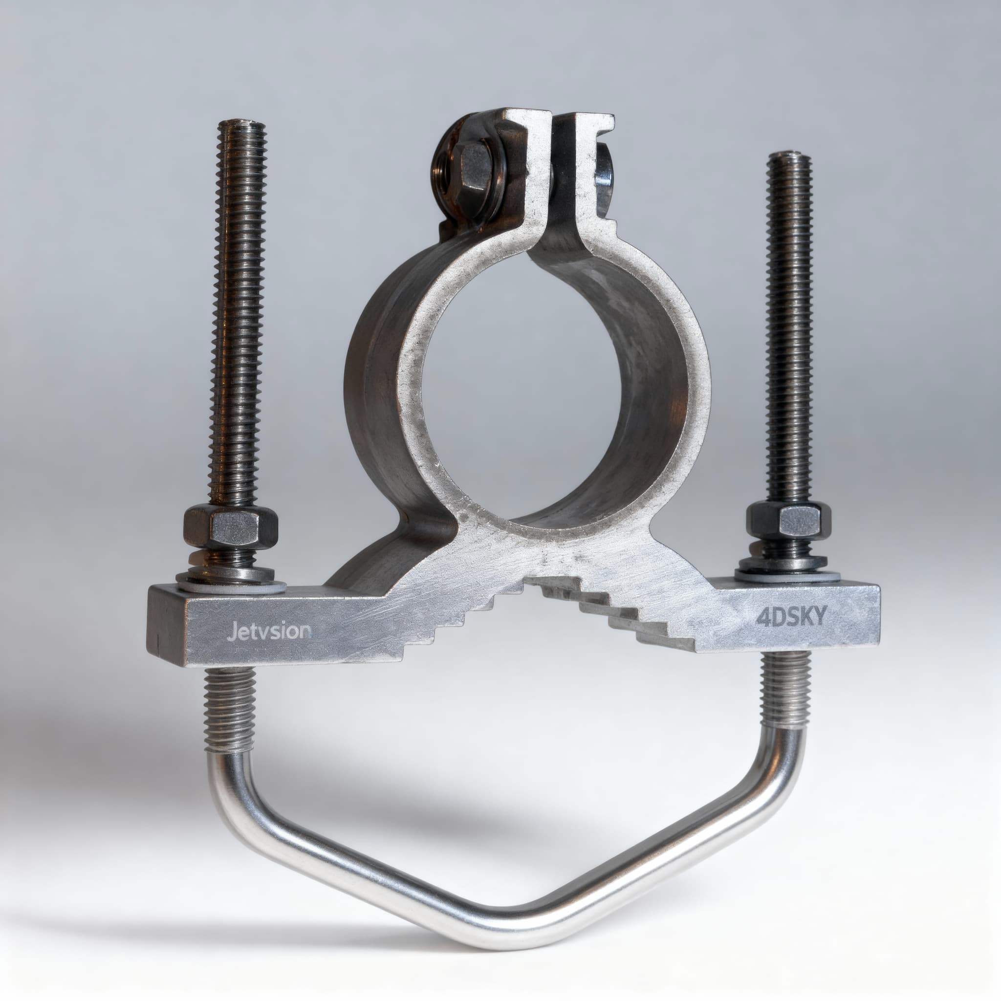
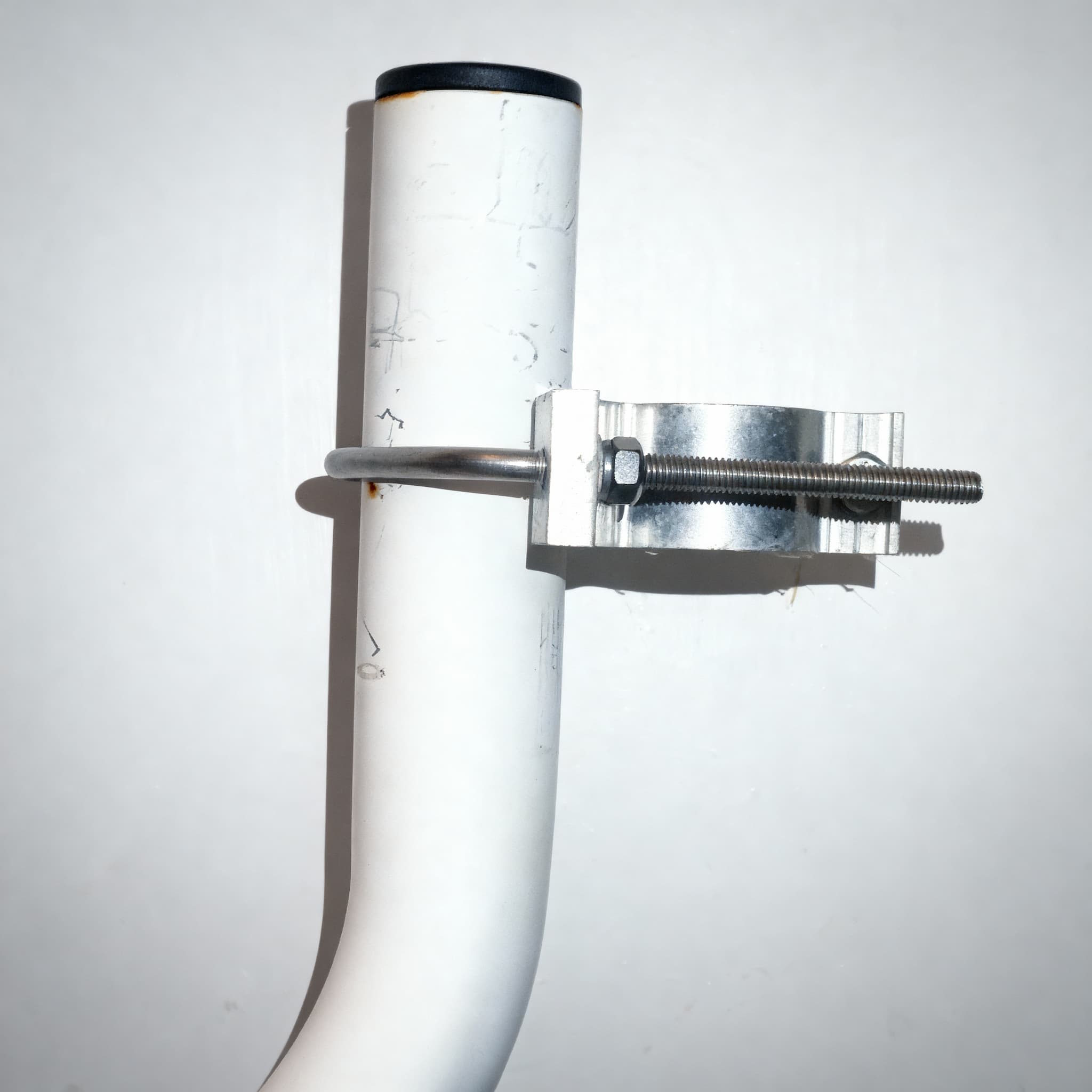
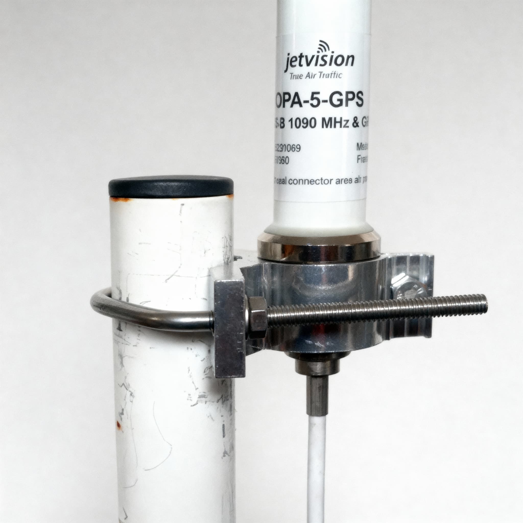
.jpg)
.jpg)


Important: only use the ethernet method to setup your Jetvision. Do not use the micro-USB as this does not work.Tip: If you plan to use wi-fi to connect your device, use ethernet to configure your wi-fi network first, then move your device closer to your antennas, and complete setup.
Key steps:
If you are having any issues, please see our troubleshooting guide here, or open a ticket on our Discord channel, and a member of our team will be in touch as soon as possible to help you.
Follow the instructions in the link below to register your sensor on the 4DSKY app. Receive and track your bonus points, and view aircraft and sensor metadata in real-time, all within a modern 3D interface.
Please refer to the following video to help you connect your device to Neuron:
Summary
To connect your sensor to the Neuron network, go to https://explorer.neuron.world and create your device account and obtain a private key.
Once you have your device account number and private key, you will need to insert that into your sensor. To do this, you must connect to your sensor by visiting the following IP address and following the wizard:
http://<your-sensor-IP>:1337 (replace <your-sensor-IP> with your sensor's local IP address)
You can find out your sensors local IP address by pressing the button on front of your sensor a few times until you reach the "LAN" or "Wi-Fi" screen (depending on your connection type). <your-sensor-IP> is the IP address at the top of the respective screen. It should have a format of 192.168.1.XXX
Once complete, your sensor will appear in the 4DSKY Explorer. You may need to wait 5 minutes for it to refresh.
